Key Hardware
Core Components
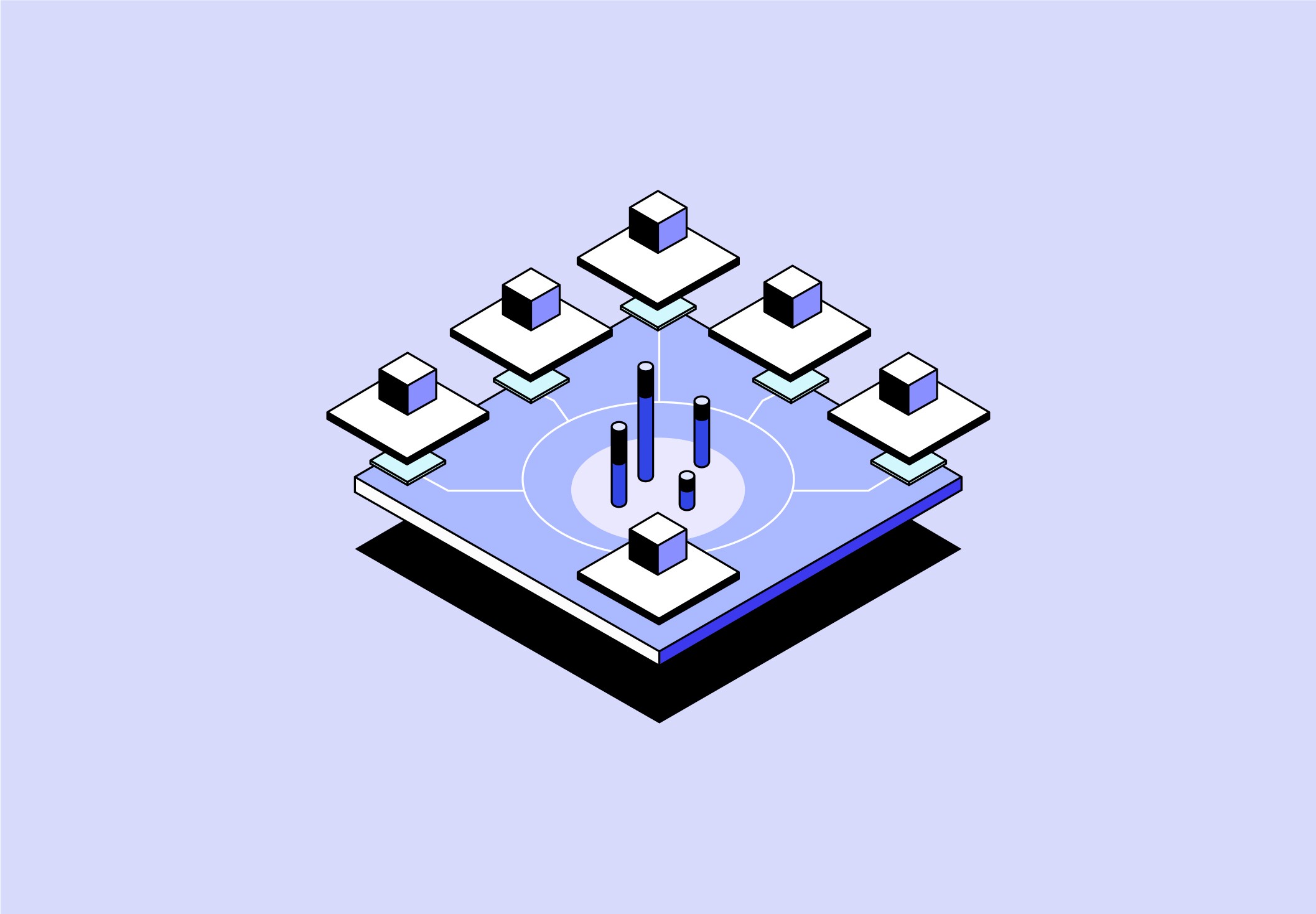
AERIS is organized into major component groups that work together as one system: air intake, condensation, water treatment, potable storage, power, controls, sensing, structure, and service access. Each component has a specific job, but the strength of the product comes from how these parts connect into a safe, repairable, disaster-ready water platform.
1. Outer Shell
The outer shell is the protective body of AERIS. It protects the internal systems from dust, rain, impact, and rough transport.
AERIS uses a rugged white HDPE-style shell because the material is lightweight, impact-resistant, washable, and resistant to corrosion. The shell is not just cosmetic. It separates dirty air, clean water, heat, and electrical zones so the system can operate safely. The shell includes:
top air intake opening
fan and vent openings
front dispensing area
side service doors
rear exhaust zone
lower battery/power access area
The shell gives the product a clean, trustworthy appearance while still making it durable enough for disaster response.
2. Internal Frame
The internal frame is the skeleton of the product. It supports the heavy components, including the compressor, battery, water tank, filters, and fans.
AERIS uses a metal frame because the outer shell alone cannot carry the full structural load. The frame keeps the parts aligned, reduces vibration, and protects components during movement. The frame also creates modular zones:
air system zone
thermal system zone
water treatment zone
power zone
control/interface zone
This makes the system easier to build, repair, and explain.
3. Wheels and Mobility Base
The wheel system makes AERIS portable. Since the unit contains a compressor, battery, tank, and filtration system, it is too heavy to carry casually. The base uses rugged caster wheels or large rolling wheels so one person can move the unit across shelters, clinics, relief camps, or temporary deployment sites. The mobility base includes:
wheel mounts
locking casters
rubber feet
lower frame support
vibration isolation
The wheels support the product’s disaster-use purpose: water production can move where people need it most.
4. Air Intake Opening
The air intake is where the system begins. It allows ambient air to enter the machine so moisture can be extracted.
AERIS uses a top/front intake because this placement gives the unit access to cleaner airflow while keeping it separate from the rear or side exhaust. The intake is shaped to bring air into the system without letting rain, large debris, or splash enter directly.
The intake is large because atmospheric water generation requires a lot of airflow. More usable airflow means more opportunity to collect humidity.
5. Intake Louver / Rain Baffle
The intake louver controls how air enters the system. It blocks direct rain and debris while still allowing airflow.
The rain baffle is important because AERIS may be used outside or in damaged environments. It prevents water from entering the intake path in an uncontrolled way. Rainwater can still be treated if intentionally collected, but random splash entering the air system can damage filters, sensors, or internal components.
6. Coarse Debris Screen
The coarse debris screen is the first filter layer. It removes large contaminants before they reach the more sensitive filters. It blocks:
insects
leaves
hair
large dust clumps
fibers
visible debris
This screen protects the pre-filter and fine filter from clogging too quickly. It also makes field maintenance easier because large debris can be cleaned off quickly.
7. Replaceable Dust / PM Pre-Filter
The pre-filter captures larger dust and particulate matter. It is replaceable or washable, depending on the version.
Its purpose is to reduce the load on the fine particle filter. In disaster zones, dust, ash, smoke, and construction debris can quickly clog a system. The pre-filter acts as the first serviceable defense layer.
This component is designed for fast replacement because it is one of the most frequently maintained parts.
8. Fine Particle Filter
The fine particle filter removes smaller airborne particles before air reaches the cooling system. This protects:
evaporator coil
condensate tray
water path
internal sensors
airflow channels
The fine filter helps reduce contamination risk because the water forms directly from the air passing through this path. Cleaner air entering the evaporator means cleaner condensate entering the water system.
9. Air Quality Sensor Gate
The air quality sensor gate decides whether the system is allowed to produce water. It measures:
PM2.5
PM10
VOC levels
temperature
relative humidity
This component is critical because AERIS does not assume all air is safe. If the air is polluted, smoky, chemically contaminated, or too low in humidity, the system changes behavior. The sensor gate supports three modes:
Safe Production: system runs normally
Caution: system runs with reduced output and warnings
Lockout: system stops atmospheric production
This protects users from unsafe water and prevents the machine from wasting energy in poor conditions.
10. Intake Fan / Blower
The intake blower pulls air through the filters and across the evaporator coil.
AERIS uses a controlled blower instead of relying on passive airflow because the system needs consistent air movement. The blower adjusts airflow depending on humidity, filter resistance, and system demand. It works with the controller to balance:
water output
energy use
noise
filter loading
condensation efficiency
Without the blower, the system cannot reliably move enough air to produce water.
11. Evaporator Coil
The evaporator coil is the cold surface where water is created. Filtered air passes across the coil. The coil cools the air below its dew point, causing moisture in the air to condense into droplets. This is the core conversion stage:
humid air → cooled surface → liquid water
The evaporator uses a hydrophilic surface so droplets drain cleanly into the condensate tray instead of sticking to the coil. This improves collection efficiency and reduces stagnant moisture buildup.
12. Compressor
The compressor powers the refrigeration loop. It compresses refrigerant and moves it through the cooling system. The compressor is one of the most important and energy-demanding components. It allows the evaporator coil to stay cold enough to condense water from the air. AERIS uses the compressor in coordination with:
evaporator temperature sensors
humidity readings
battery level
condenser temperature
pressure sensors
This prevents wasted energy and protects the system from overheating or freezing.
13. Condenser Coil
The condenser coil releases heat from the refrigeration cycle. As the compressor moves refrigerant through the system, heat must be removed. The condenser coil rejects that heat into the outside air. The condenser is placed away from the intake so the system does not pull its own hot exhaust back into the air path. This separation keeps production efficient.
14. Condenser Fan
The condenser fan pushes air across the condenser coil to remove heat. It directs hot air out through the rear or side exhaust. This fan is part of the thermal management system and helps the compressor operate safely. If heat is not removed properly, the system becomes less efficient and can shut down to protect itself.
15. Expansion Device
The expansion device controls refrigerant pressure before it reaches the evaporator coil. It allows the refrigerant to drop in pressure and temperature, creating the cold condition needed for condensation. This part is small, but it is essential to the refrigeration cycle. Without it, the evaporator cannot become cold enough to extract moisture from the air.
16. Refrigerant Lines
The refrigerant lines connect the compressor, condenser, expansion device, and evaporator. They carry refrigerant through the closed cooling loop. These lines must handle pressure, vibration, and temperature changes. The refrigerant loop is sealed and separated from the water path. Users do not interact with this system during normal maintenance.
17. Condensate Collection Tray
The condensate tray catches water droplets that form on the evaporator coil. AERIS uses a sloped stainless steel tray because the water must drain cleanly without pooling. Pooling water can create sanitation issues and reduce system trust. The tray sends raw condensate into the raw water buffer. Its job is to:
collect water
prevent leaks
avoid standing water
keep water away from electronics
guide water into treatment
18. Raw Water Buffer
The raw water buffer stores newly collected condensate before purification. At this stage, the water is not drinkable yet. It has been collected from air, but it still needs filtration, disinfection, and verification. The buffer stabilizes flow because condensation does not always happen at a constant rate. It gives the pump a consistent source of water to send through the treatment stages.
19. Transfer Pump
The transfer pump moves water from the raw buffer through the purification system. It creates enough pressure to push water through:
sediment filter
carbon filter
UV-C chamber
mineral cartridge
water quality sensors
The pump is controlled by the microcontroller. It only runs when water is available, treatment is ready, and the system is safe.
20. Solenoid Valves
Solenoid valves control where water flows. They open and close electronically based on system logic. They manage:
treatment flow
recirculation flow
dispense lockout
drain/purge flow
sanitation routines
These valves help separate raw water from clean water and prevent unsafe water from reaching the user.
21. Check Valves
Check valves prevent water from flowing backward. This is important because raw water and potable water must never mix. Check valves keep the water moving in one direction through the treatment train. They also protect the pump and help maintain system pressure.
22. Sediment Filter
The sediment filter removes fine physical particles from the collected water. Even after air filtration, small particles may still enter through condensation surfaces or internal pathways. The sediment filter polishes the water before it reaches the carbon and UV stages. It protects downstream components and improves water clarity.
23. Activated Carbon Filter
The activated carbon filter improves taste and reduces odors and some organic compounds. This stage is important because air-derived water can still pick up compounds from the environment or from internal materials. Carbon helps improve user trust by making the water taste and smell cleaner. Carbon is not treated as a universal chemical solution. It works as one barrier in a larger safety system.
24. UV-C Disinfection Reactor
The UV-C reactor disinfects the water using ultraviolet light. Water passes through a UV chamber where UV-C energy targets microorganisms. This reduces microbial risk without adding chemicals. The reactor includes:
UV-C lamp or LED
flow chamber
reflective interior
UV driver
shielding
UV confirmation sensor
safety interlock
The system verifies that UV is functioning before allowing water to move forward as potable.
25. Mineralization Cartridge
The mineralization cartridge adds minerals back into the treated water. Condensed water is naturally low in minerals, which can make it taste flat. Mineralization improves taste and makes the water feel more familiar to drink. The cartridge may add:
calcium
magnesium
alkaline mineral media
This component supports both water quality and user acceptance.
26. Water Quality Sensor Module
The water quality sensor module verifies that treated water is safe enough to store and dispense. It measures:
turbidity
conductivity / TDS
flow
UV status
water level
If water quality is outside the system’s thresholds, AERIS prevents dispensing and alerts the user. This is what makes the system trustworthy: the user is not asked to guess whether the water is safe.
27. Potable Tank
The potable tank stores treated drinking water. AERIS uses an opaque food-grade tank to reduce light exposure and prevent microbial regrowth. The tank is placed near the center of the system because it is the clean-water core. The tank includes:
level sensor
vent filter
outlet to tap
recirculation connection
cleaning access
overflow protection
It is downstream of all treatment stages, meaning only verified water enters this storage zone.
28. Sterile Vent Filter
The sterile vent filter allows air to enter the potable tank as water leaves.
Without a vent, dispensing can create a vacuum. But the tank cannot simply pull in dirty outside air. The vent filter allows pressure balance while reducing contamination risk.
29. Recirculation Loop
The recirculation loop prevents stored water from sitting still for too long. It periodically moves water through a controlled path, often back through UV treatment. This reduces stagnation and helps maintain water quality over time. The loop includes:
recirculation pump or shared pump
return tubing
valves
UV path
timed control logic
30. Dispense Tap / Fill Port
The tap is the main user interaction point. It dispenses water only when the system confirms:
water is treated
UV is working
tank water is safe
no lockout is active
The tap includes a recessed fill area and drip tray to keep the front clean. The dispense point is protected because it is the final clean-water endpoint.
31. Drip Tray
The drip tray catches spills and overflow under the tap.It keeps the front of the unit clean and reduces mess around the fill area. In emergency or shared-use environments, this helps maintain hygiene.
32. Solar PV Input
The solar input allows AERIS to connect to solar panels. Solar power supports off-grid use and reduces dependence on damaged infrastructure. It feeds energy into the charge controller rather than directly powering every component. Solar acts as a recharge and daytime support source.
33. External AC/DC Input
The external power input allows charging or operation from wall power, generator power, vehicle power, or a field power source. This gives AERIS flexibility because solar alone is not always enough, especially at night, indoors, or during poor weather.
34. Input Protection System
Input protection prevents electrical damage. It includes:
fuses
surge protection
reverse-polarity protection
circuit breakers
overcurrent protection
This protects the battery, controller, sensors, and user.
35. MPPT Charge Controller
The MPPT charge controller manages solar charging. It extracts the best usable power from the solar panels and safely charges the battery. This is important because sunlight changes constantly. MPPT helps the system use available solar energy more efficiently.
36. LiFePO4 Battery Pack
The LiFePO4 battery stores power for off-grid operation. AERIS uses LiFePO4 because it is stable, durable, and well-suited for repeated charging cycles. It powers:
compressor
fans
pumps
UV-C
sensors
display
control board
The battery sits low in the unit to improve stability.
37. Battery Management System
The BMS protects the battery. It monitors:
cell voltage
temperature
current
charging
discharging
cell balancing
If the battery gets too hot, too low, or overloaded, the BMS shuts down or limits operation.
38. DC Bus
The DC bus distributes power from the battery and power inputs to the rest of the system. It acts as the electrical backbone. The DC bus feeds:
compressor drivers
fan drivers
pump circuits
UV system
sensors
microcontroller
interface
39. DC-DC Converters
DC-DC converters create the correct voltage levels for different parts. AERIS uses different voltages because sensors, fans, pumps, and controls do not all run on the same power. Example power levels:
high power for compressor
24V for pumps/fans
12V for actuators
5V for sensors/display
3.3V for microcontroller logic
40. Microcontroller / Control Board
The microcontroller is the brain of AERIS. It reads sensor data, makes decisions, and controls the physical systems. It receives data from:
air sensors
water sensors
tank sensors
battery sensors
UV sensors
filter sensors
door switches
leak sensors
It controls:
compressor
fans
pumps
valves
UV-C
display
lights
buzzer
dispense lock
41. HMI Display
The HMI display communicates system status to the user. It shows:
water available
safe-to-drink status
battery level
air quality
humidity level
production status
filter life
alerts
42. Status LEDs
The status LEDs provide quick visual feedback from a distance. A simple system works best:
green = safe / ready
yellow = caution / maintenance
red = unsafe / lockout
This matters in disaster settings because users may not have time to read detailed screens.
43. Buttons and Controls
Physical controls allow users to operate the system. They include:
power button
start/stop control
dispense control
maintenance reset
alert mute
mode button
The controls stay simple because the product may be used by many different people in stressful environments.
44. Buzzer / Audio Alert
The buzzer provides sound feedback for warnings and system states. It can alert users when:
water is ready
tank is full
battery is low
filter needs replacement
water is unsafe
service panel is open
a fault is active
45. Telemetry Module
The telemetry module allows AERIS to send performance data to a dashboard or app. It can communicate:
water produced today
battery level
air quality
filter life
fault history
location/status for deployed units
This is useful for NGOs, clinics, and disaster-response teams managing multiple units.
46. Safety Interlocks
Safety interlocks prevent unsafe operation. Examples:
UV chamber open → UV shuts off
service panel open → compressor pauses
unsafe water → tap locks
hazardous air → atmospheric production stops
low battery → reduced mode
leak detected → water system shuts down
tank full → production stops
These interlocks make the system safer for both users and service workers.
47. Gaskets and Seals
Gaskets and seals keep air, water, dust, and electronics separated. They are used around:
service panels
tank lid
intake ducting
electrical bay
water path
filter drawers
48. Wiring Harness
The wiring harness organizes power and signal connections. It connects:
sensors
pumps
fans
display
controller
battery
charge controller
valves
UV system
49. Tubing and Fittings
Food-grade tubing moves water through the system. Tubing connects:
condensate tray
raw buffer
pump
filters
UV chamber
mineral cartridge
potable tank
tap
Fittings and clamps keep the water path sealed and serviceable.
50. Service Labels and QR Guide
Labels and QR codes help users maintain the system correctly. They identify:
filter replacement points
intake and exhaust zones
safe water status
power input locations
maintenance steps
warning zones
This makes the product easier to use in the field, especially when trained technicians are not always available.
Core Component Summary
AERIS works because each component has a clear role:
Air components bring in usable air and block contamination.
Thermal components cool the air and create condensation.
Water components collect, clean, verify, store, and dispense potable water.
Power components allow off-grid operation.
Control components make safety decisions.
Structural components protect the system and make it serviceable.
Together, these parts create a complete atmospheric water system that is not only functional, but safe, repairable, and realistic for emergency deployment.


