Internal Architecture
Inside the System

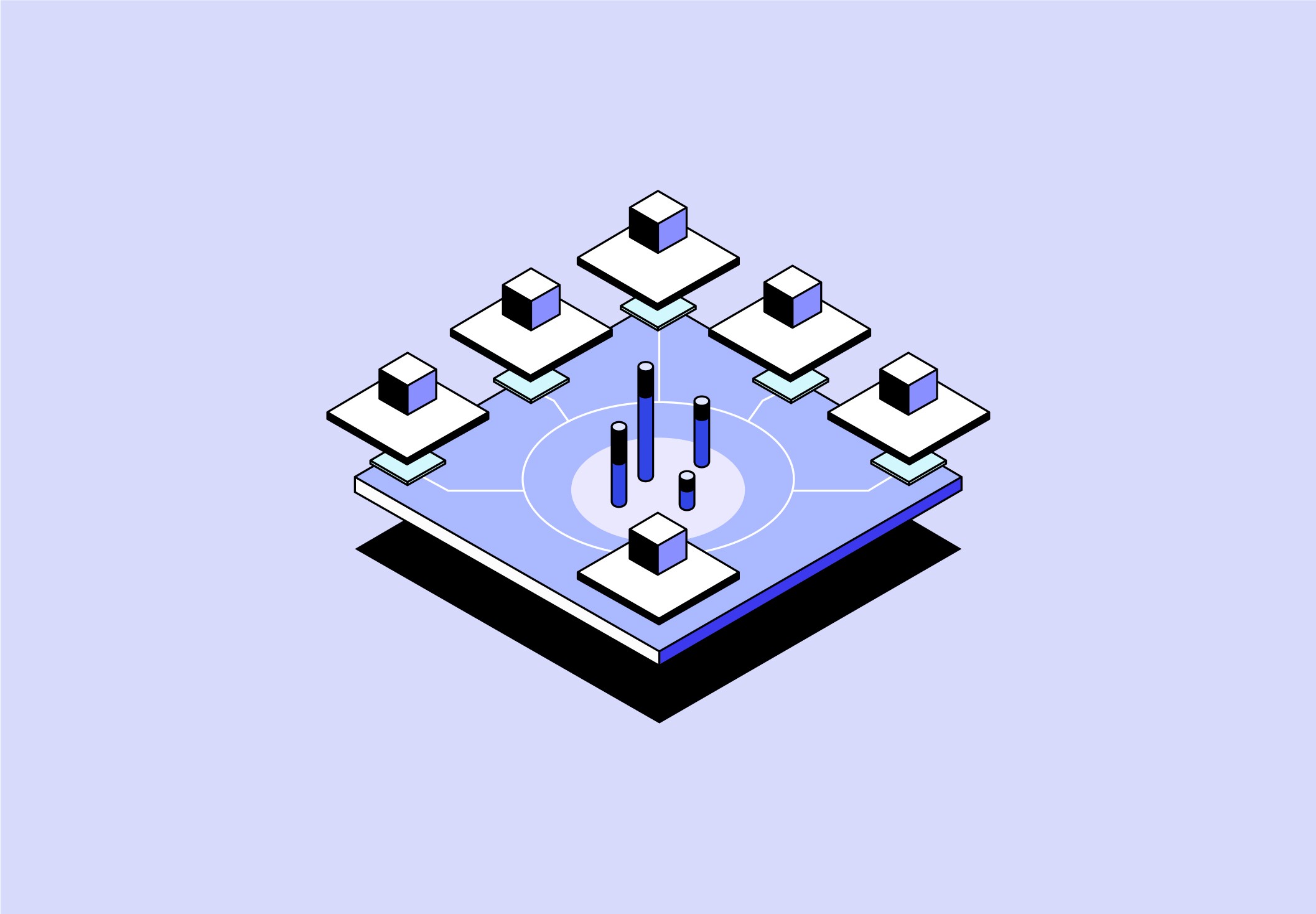
AERIS is built like a layered machine: air system on top, water system around the central tank, power system at the bottom, and control logic connecting everything. The system is modular so filters, cartridges, batteries, sensors, and serviceable parts can be accessed without taking the whole unit apart. Your project document defines this as a ruggedized atmospheric water and emergency treatment platform with air-quality gating, multi-barrier water treatment, and field-serviceable maintenance.
1. Structural Frame + Body Architecture
The internal structure is the skeleton of the product. AERIS does not rely on the outer shell alone to hold the heavy parts. Inside, it needs a powder-coated aluminum or stainless steel frame that supports the compressor, battery, potable tank, filters, pumps, fans, and panels. The frame holds the system in separated zones:
Top zone: air intake, filters, fans, evaporator coil
Middle zone: condensate tray, raw water buffer, potable tank, water treatment cartridges
Side zones: replaceable filters, UV chamber, pump, valves, service panels
Bottom zone: LiFePO4 battery, BMS, MPPT, fuse block, wiring harness
Rear/side zone: condenser, compressor, hot air exhaust
This layout matters because the system deals with dirty air, clean water, electricity, heat, and vibration at the same time. Those zones cannot be randomly mixed. The water path must stay isolated from the electronics bay, and hot condenser exhaust must stay separated from the intake so the machine does not recirculate its own heat.
2. Outer Shell + Service Panels
The shell is the protective skin. For AERIS, the shell is rugged, washable, and weather-resistant, not just visually clean. Shell materials:
Rotomolded HDPE: Strong, impact-resistant, low-cost, and commonly used in coolers, water tanks, and industrial containers.
Thermoformed ABS/PC blend: Cleaner finish, still durable, easier for prototype-level fabrication.
EPDM or silicone gaskets: Used around service panels, access doors, electrical compartments, and water zones.
The shell includes:
top intake opening with protective mesh
side service panels
rear exhaust grille
front tap recess
lower power access panel
sealed electronics compartment
removable filter drawer
wheel mounts and tie-down points
The goal is not to hide the system, but to make it safe, maintainable, and protected.
3. Air Intake System
The air system is the first major subsystem. Its job is to pull in ambient air, remove particles, measure air quality, and direct usable air into the condensation chamber. The air path is:
Ambient Air → Intake Louver → Debris Screen → Coarse Pre-Filter → Fine Particle Filter → Air Quality Sensor Gate → Intake Fan / Blower → Evaporator Coil
Intake louver / rain baffle: This is the first exterior opening. It allows air in while helping block rain, splash, leaves, insects, and direct debris.
Stainless mesh debris screen: This catches large contaminants before they reach the filters.
Coarse pre-filter: This is the first replaceable or washable filter. It protects the more expensive fine filter from clogging too quickly.
Fine particle filter: This is the higher-efficiency filter stage. It protects the evaporator coil and condensate tray from smaller airborne particles.
Air quality sensor gate: This is one of the most important parts of the product. It measures whether the air should be used for water generation. Sensors include:
PM2.5 sensor
PM10 sensor
VOC proxy sensor
temperature sensor
relative humidity sensor
filter differential pressure sensor
The sensor gate sends data to the microcontroller. If air is safe, the machine continues. If air is marginal, it runs in caution mode. If VOCs or dangerous contamination are too high, it enters lockout mode.
Intake fan / blower: AERIS uses a centrifugal EC or BLDC blower instead of a cheap axial fan. A blower is better because it can pull air through filters and ducts with more pressure control. Its job:
maintain airflow through the intake
push air across the evaporator coil
adjust speed based on humidity, filter resistance, and battery state
4. Refrigeration + Condensation System
This is the “engine” that turns air into water. AERIS uses a vapor-compression cooling system, similar to a dehumidifier or air conditioner. Your document identifies vapor-compression condensation as the primary architecture because it is mature, practical, manufacturable, and easier to maintain. The refrigeration loop includes:
compressor
condenser coil
condenser fan
expansion valve or capillary tube
evaporator coil
refrigerant lines
filter drier
pressure sensors
temperature sensors
vibration isolators
Compressor: The compressor pressurizes refrigerant and moves it through the cooling loop. It is one of the highest-power components in the system. A variable-speed compressor would be ideal because the system can adjust output depending on:
humidity
ambient temperature
battery level
tank level
thermal load
Condenser coil: The condenser rejects heat from the refrigeration cycle. Hot refrigerant passes through the condenser and releases heat to the outside air.
Condenser fan: This fan moves air across the condenser coil to remove heat. It exhausts toward the rear or side, away from the intake.
Expansion device: This controls refrigerant pressure before it enters the evaporator. It can be:
capillary tube
thermostatic expansion valve
electronic expansion valve
The more advanced option is an electronic expansion valve because it allows smarter control.
Evaporator coil: This is the cold coil where water is created. Filtered air passes over the coil. When the air temperature drops below its dew point, moisture condenses into liquid droplets.
Hydrophilic coating: The evaporator coil has a hydrophilic coating so water sheets off the coil cleanly instead of clinging to the fins. This improves:
drainage
output
sanitation
reduced pooling
Defrost logic: If the coil gets too cold, ice can form. AERIS temperature sensors and control logic to detect icing and trigger a defrost routine.
5. Condensate Collection System
Once water forms on the evaporator coil, it drips into the condensate tray. The condensate collection area includes:
316L stainless steel drip tray
sloped drain geometry
antimicrobial surface treatment
drain outlet
raw water tubing
leak sensor
overflow protection
Condensate tray: This tray is made from 316L stainless steel because it is corrosion-resistant and safe for water-contact zones. The tray:
slopes toward the drain
avoids corners where water sits
prevents pooling
keeps water away from electronics
is easy to clean
Drain outlet: The drain moves raw condensate from the tray into the raw water buffer.
Leak sensor: A leak sensor sits below the water path or in the base pan. If water escapes the tray, tubing, filters, or tank, the system can shut down before it reaches electronics.
6. Raw Water Buffer
The raw water buffer is a small temporary reservoir between collection and purification. It exists because condensation is not always constant. Sometimes water forms slowly, sometimes faster depending on humidity and temperature. The buffer stabilizes that uneven flow before water moves through the filters. It includes:
raw water reservoir
level sensor
tubing inlet from condensate tray
pump outlet
overflow protection
cleaning access
7. Water Pump + Flow Control
The pump moves water through the purification stages. Pump types:
Diaphragm pump: Good for controlled pressure and small water systems.
Peristaltic pump: Good because water only touches the tubing, but may have lower flow.
Small DC pressure pump: Common, serviceable, and easy to power from the DC bus.
The flow-control system includes:
pump
solenoid valves
check valves
flow sensor
pressure sensor
tubing clamps
food-grade tubing
Check valves: These prevent backflow so raw water cannot migrate into clean water zones.
Solenoid valves: These open and close different water paths. They control:
treatment flow
recirculation
drain/purge mode
dispense lockout
sanitation mode
Flow sensor: This confirms water is actually moving through the treatment path.
8. Water Treatment System
The water treatment system is what makes AERIS credible. The system does not assume condensed water is clean. It treats the condensate through multiple barriers. The treatment path is:
Raw Water Buffer → Pump → Sediment Filter → Activated Carbon Filter → UV-C Reactor → Mineralization Cartridge → Water Quality Check → Potable Tank
Sediment polish filter: This removes fine particulate residue from the collected water. It protects downstream components and improves clarity.
Activated carbon filter: This improves taste and odor and reduces some organic compounds. It is useful for:
taste issues
odors
some VOC-related compounds
organic residue
Important: carbon is helpful, but not a universal chemical purifier. This is why AERIS also needs air-quality lockout logic.
UV-C disinfection reactor: The UV-C chamber exposes water to ultraviolet light to reduce microbial risk. It includes:
UV-C lamp or LED module
quartz sleeve or flow chamber
reflective housing
UV driver
shielding
interlock
UV intensity sensor
The UV system is not be assumed to work just because it is powered on. It needs confirmation through a UV status or intensity sensor.
Mineralization cartridge: Condensed water can taste flat because it has very low mineral content. The mineral cartridge adds minerals back into the water. It uses:
calcium media
magnesium media
alkaline mineral media
Its purpose is not only health perception, but user acceptance. People are more likely to trust and drink water that tastes normal.
9. Water Quality Verification
Before treated water reaches the potable tank, AERIS verifies that the water meets internal thresholds. Sensors include:
conductivity / TDS sensor
turbidity sensor
flow sensor
UV confirmation sensor
temperature sensor
Conductivity / TDS sensor: This checks the dissolved mineral level. It helps confirm that mineralization is working and that water is not behaving unexpectedly.
Turbidity sensor: This detects cloudiness or suspended particles.
UV confirmation sensor: This confirms the disinfection stage is active and effective enough to allow dispensing. If the water fails verification, the system:
stop dispensing
recirculate water
trigger maintenance
flush/purge
enter lockout mode
10. Potable Tank
The potable tank is the central clean-water storage unit. Made of Opaque food-grade HDPE, is:
sealed
opaque
smooth inside
cleanable
removable or serviceable
isolated from electronics
downstream of all treatment
The tank includes:
level sensor
sterile vent filter
outlet to tap
recirculation connection
cleaning port
overflow cutoff
Why opaque? Light can encourage biological growth. An opaque tank helps keep treated water more stable.
Vent filter: As water leaves the tank, air must replace the volume. The vent filter allows pressure equalization without pulling dirty air directly into the potable tank.
Tank level sensor: This tells the controller:
how much water is available
when to stop production
when to show “tank full”
when to protect the pump from running dry
11. Dispense System
The dispense system is the user-facing endpoint.
It includes:
front tap
bottle fill port
dispense line
drip tray
tap sanitation shield
optional electronic dispense valve
dispense lockout
The tap only work when water is confirmed safe. That means the dispense system is not just a faucet. It is part of the safety architecture. If water quality fails or UV is not verified, the system locks dispensing and show a warning.
12. Recirculation + Anti-Stagnation Loop
AERIS includes a recirculation loop to reduce stagnant water risk. This loop can move water from the potable tank back through UV or through a controlled circulation path.
It includes:
recirculation pump
return tubing
timed valve control
UV re-treatment path
sanitation routine
13. Power System
The power system makes AERIS deployable in disaster settings. Power flow:
Solar PV Input + External AC/DC Input → Input Protection → Power Path Manager → MPPT Charge Controller → LiFePO4 Battery + BMS → Main Disconnect → DC Bus → DC-DC Converters → Loads
Solar PV input: Connects to fold-out or detachable solar panels.
External AC/DC input: Allows charging from a wall outlet, generator, vehicle system, or external power supply.
Input protection: Protects the system from:
reverse polarity
overload
voltage spikes
short circuits
incorrect power connections
MPPT charge controller: Optimizes solar charging by extracting the most usable energy from the panels.
LiFePO4 battery pack: This stores energy for off-grid operation. LiFePO4 is a strong fit because it has:
better thermal stability
long cycle life
safer chemistry compared to many lithium options
good rugged field performance
BMS: The Battery Management System protects the battery by monitoring:
cell voltage
temperature
current
charge state
overdischarge
overcharge
balancing
DC bus: The DC bus distributes power to the system loads. Loads include:
compressor
intake fan
condenser fan
pump
UV-C reactor
sensors
microcontroller
HMI display
valves
telemetry
DC-DC converters: Different parts need different voltages. Example:
compressor: higher DC or inverter-controlled power
fans/pumps: 12V or 24V
sensors: 5V or 3.3V
microcontroller: 3.3V or 5V
display: 5V or 12V depending on type
14. Microcontroller + Control PCB
The microcontroller is the brain of AERIS. It receives sensor input, runs logic, controls actuators, manages safety, and communicates with the UI. Inputs include:
PM sensor
VOC sensor
temperature sensor
humidity sensor
evaporator temperature
condenser temperature
pressure sensors
turbidity sensor
conductivity/TDS sensor
UV confirmation sensor
tank level sensor
battery SOC
filter pressure drop
door/service interlocks
leak sensor
Outputs include:
compressor control
fan speed control
pump activation
solenoid valve control
UV-C activation
dispense lock
screen updates
status LEDs
buzzer
telemetry data
The controller decides whether the system is in:
safe mode
caution mode
lockout mode
maintenance mode
low-power mode
sanitation mode
15. User Interface + HMI
The HMI is the communication layer between the complex machine and the user. It shows:
water available
water safe / unsafe
air quality state
humidity / production potential
battery status
charging source
filter life
maintenance alerts
fault messages
liters produced today
Physical interface components:
LCD or OLED display
green/yellow/red status lights
power button
start/stop button
mode button
alarm mute
QR service label
buzzer
optional app / telemetry module
The UI translates technical complexity into simple messages like:
Safe to Drink
Collecting Water
Purifying
Low Humidity
Poor Air Quality
Filter Replacement Needed
Water Unsafe — Dispense Locked
16. Sensors + Safety Interlocks
Sensors protect both the user and the machine.
Air sensors: Measure whether air is safe and productive.
Water sensors: Measure whether water is clear, treated, and ready.
Power sensors: Measure battery state, charging, current draw, and temperature.
Mechanical sensors: Check panel doors, leaks, filter loading, tank level, and overflow.
Safety interlocks: Prevent dangerous operation. Examples:
UV chamber open → UV turns off
service panel open → compressor pauses
tank full → production stops
leak detected → water system shuts down
unsafe water → dispense locks
hazardous air → atmospheric production stops
low battery → system enters reduced mode
17. Thermal + Exhaust Management
AERIS generates heat because it uses a compressor. That heat has to be managed carefully. Thermal management includes:
condenser fan
exhaust grille
separated hot-side ducting
compressor vibration mounts
electronics heat sinks
electronics cooling fan
acoustic damping
The exhaust path directs heat out the rear or side. It never blows toward the intake because warm exhaust air reduces condensation efficiency.
18. Maintenance Architecture
AERIS is designed so field workers can service the most common parts quickly. Routine service parts:
coarse pre-filter
fine particle filter
sediment cartridge
carbon cartridge
mineralization cartridge
UV module
sanitation port
drain port
battery access
fuse access
Service logic:
First access: air filter drawer
Second access: water cartridges
Third access: UV and pump
Restricted access: compressor/refrigerant bay
Separated access: battery/electrical bay
This prevents untrained users from opening dangerous areas while still making common maintenance easy.
19. How Everything Works Together
AERIS works as one connected system:
The power system wakes the controller.
The controller checks sensors: air, battery, tank, filters, UV, water quality.
If conditions are safe, the fan pulls air through filters.
The sensor gate verifies air quality and humidity.
The compressor cools the evaporator coil.
Moisture condenses and falls into the condensate tray.
Raw water moves into the buffer tank.
The pump pushes water through sediment, carbon, UV-C, and mineralization.
Sensors verify water quality.
Clean water enters the potable tank.
The UI shows water status.
The tap unlocks only when the system confirms the water is safe.
The system continues monitoring for faults, air changes, filter life, and battery level.